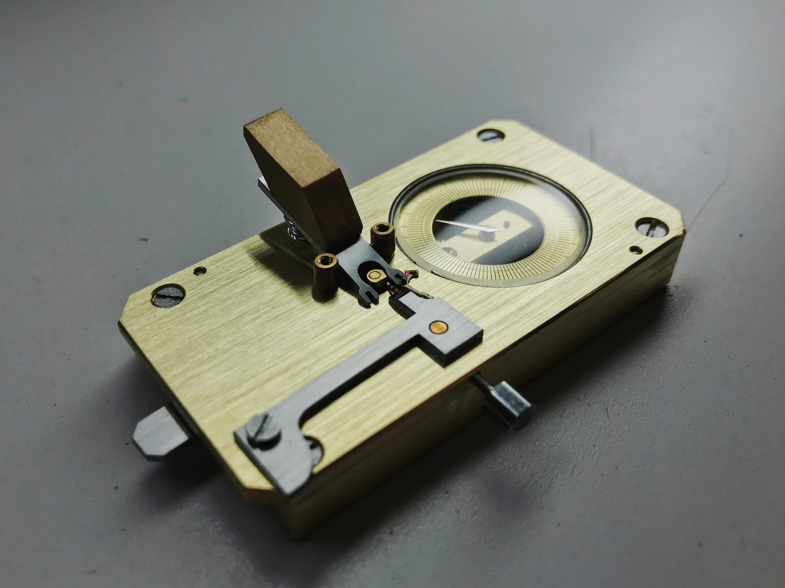
Escapement Meter: Geartrain Module

Our big second-year micromechanics project is nearing its completion.
Making the escapement meter is an excellent test of our micromechanics abilities, from sawing and filing to precision machining. This segment of the mechanism is mostly to do with machine work.
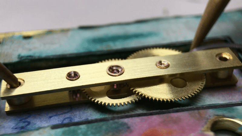
Like in a watch or clock, the heart of the escapement meter is the geartrain, which has been made into a module in this iteration; the stock model has the geartrain pivots bored into the body of the meter, which is significantly less practical to accomplish on our small watchmaker's lathes.
There are three pivoting elements, comprising two wheels and two pinions. The big wheel is driven by the pallet stone adjustment, which has its motion amplified by a multiplication geartrain, at the end of which will be a hand and a dial.
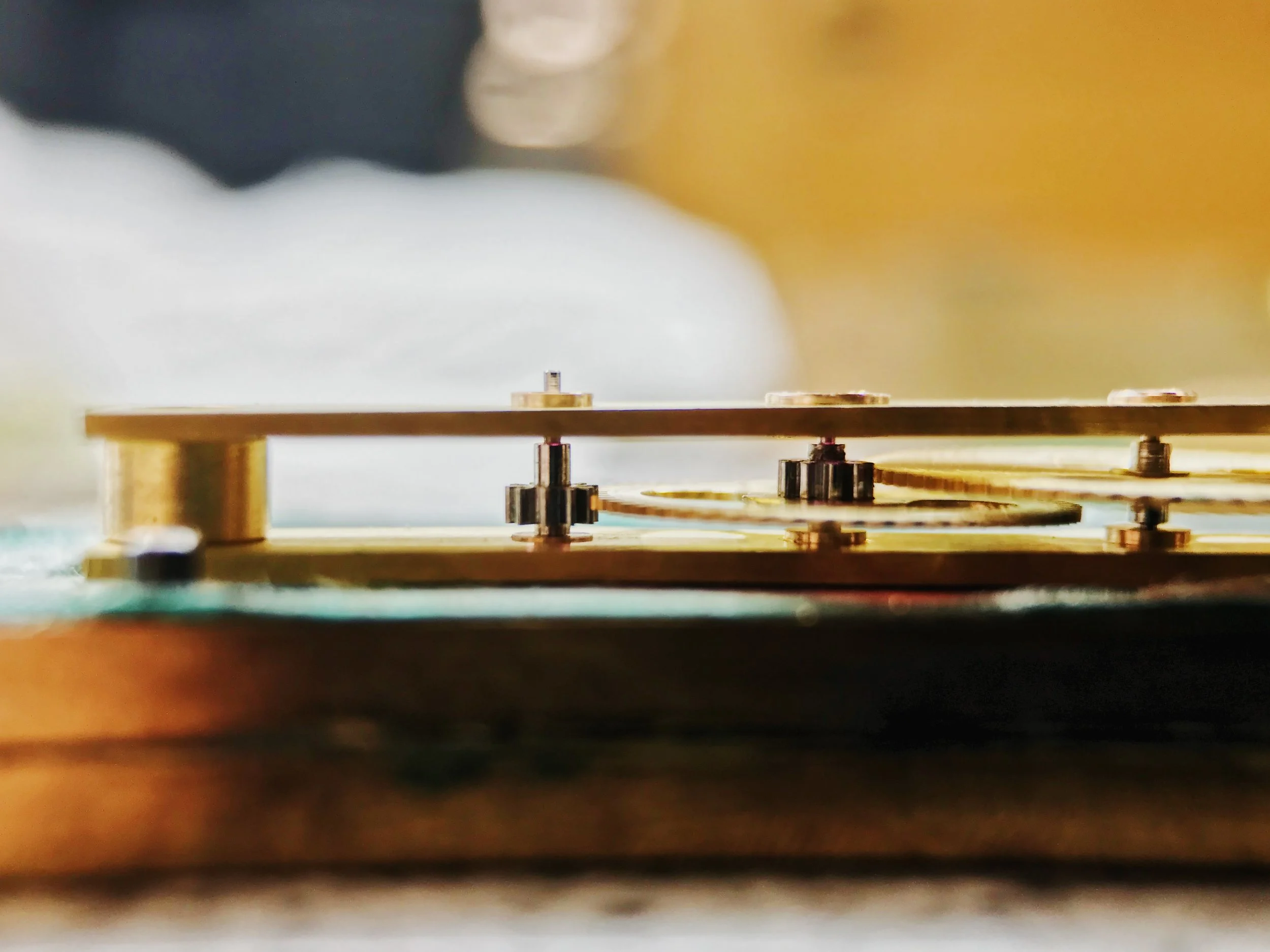
Our plans call for the geartrain pivots to simply bear in precisely-drilled holes in the plates, but that's so plain looking. Instead, I decided to pivot my components in bronze bushings (which I had handy). The bushings have the added benefit of providing adjustable endshakes and division, which can help make up for machining errors.
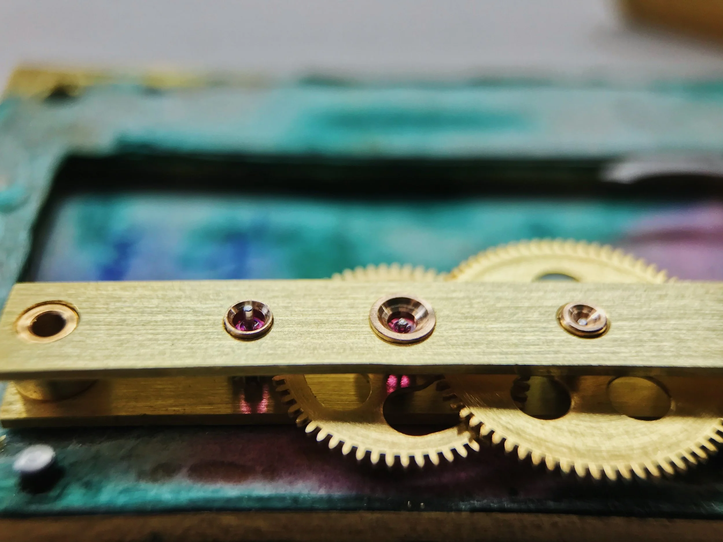
You'll notice that there are two jewels in the geartrain, instead of bushings all the way down. I'd like to say that this is purely for looks and wear resistance, but that's not entirely honest. My center wheel's bushing was loose, so I needed to fit a wider one, and my premade bushing stock didn't have anything with a larger diameter, but a small-enough pivot for this project. I could have made a bushing from scratch, but instead I modified a larger bushing to accept a jewel.
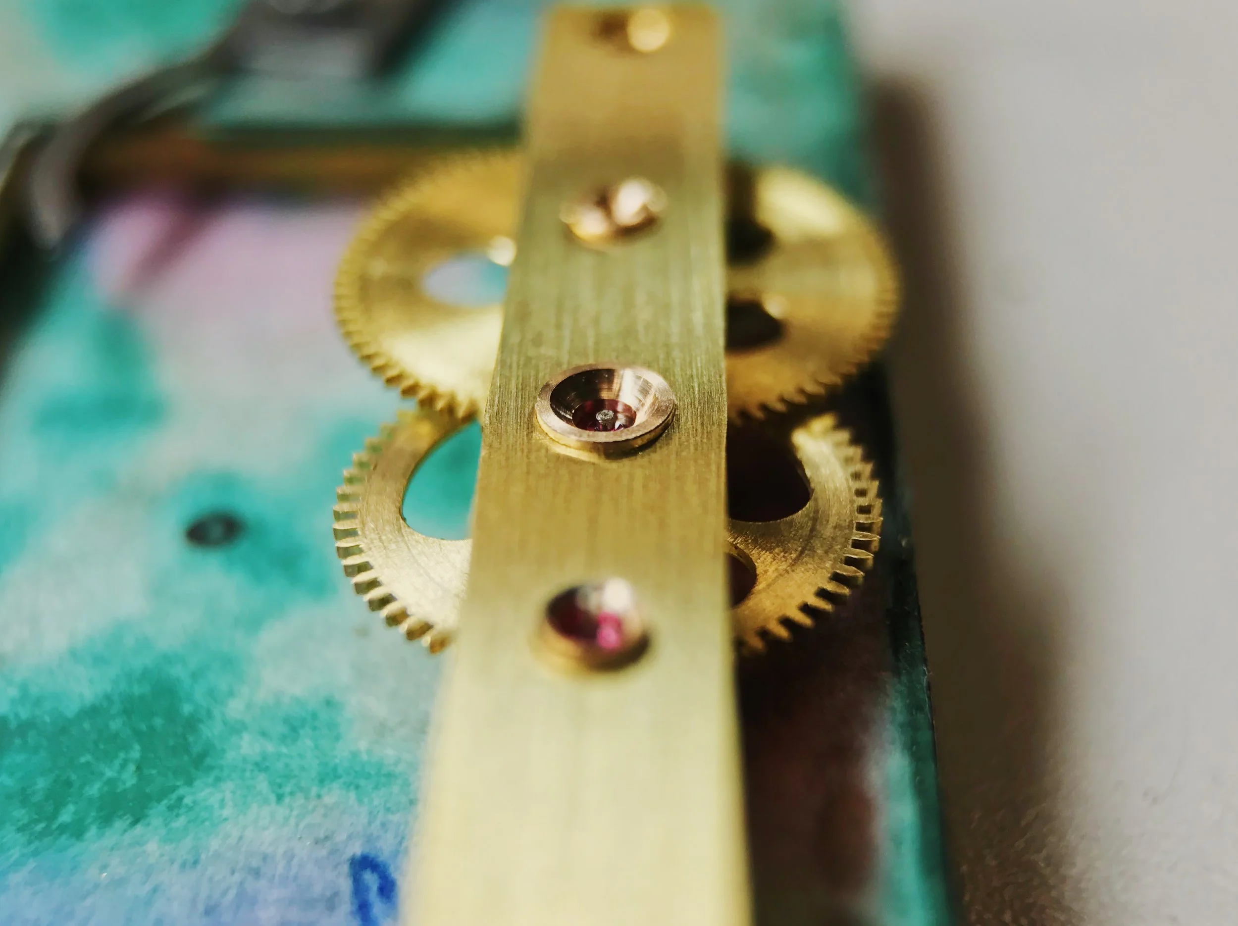
It looked silly with just one pivot being jeweled (especially one that isn't visible after assembly), so I modified the indicating pinion's bushing to accept a jewel as well. These two pivots have the highest rotational speed and are furthest from the "power," so the decreased friction and increased wear resistance will come in handy. The first wheel in the train is actually driven by hand power during some phases of use, and only ever turns a few degrees (maybe even just minutes) in operation, so a bushing is preferable (and easier to accomplish in the limited time I have available for this project.
The pivots were laid out using a depthing tool, which allows the watchmaker to find the proper distance between centers through tactile feedback. It's an excellent tool, and one that requires practice and experience more than book-learning to master.
These are 0.2 mm module wheels and pinions, which are watch-sized but not miniscule. Still, depthing errors of just a few hundredths of a millimeter could cause the whole thing to bind. Luckily, these components spin without effort.
The indicating pinion still needs a hairspring and the driving wheel needs a plunger post. After that, it's on to assembly and final finishing. Stay tuned!
Watchmaking student at the Lititz Watch Technicum, formerly a radio and TV newswriter in Chicago.